
close
Choose Your Site
Global
Social Media
Views: 0 Author: Site Editor Publish Time: 2026-08-14 Origin: Site


Industrial refrigeration and gas compression systems rarely operate at 100% design load continuously. The core engineering challenge is matching compressor output to fluctuating system demands without incurring the mechanical wear and energy penalties of frequent motor start/stop cycles. Operating a fixed-capacity compressor at part-load conditions leads to severe energy inefficiencies, compromised temperature control, and premature equipment failure. Facilities need reliable, continuous capacity modulation to optimize operational expenditure.
Utilizing the slide valve as an unloader mechanism allows the driver motor to remain running continuously while dynamically shedding or adding load. The slide valve remains the industry-standard mechanical solution for stepless capacity control. This guide evaluates the mechanics of slide valve operation, its efficiency trade-offs across different temperature ranges, and how it compares to or integrates with modern electronic control methods.
Mechanical Modulation: Slide valves adjust capacity by moving axially along the rotor casing, delaying the start of compression and bypassing uncompressed suction gas back to the inlet.
Unloaded Starting: Beyond part-load modulation, slide valves act as critical unloader mechanisms, allowing the screw compressor to start at minimum capacity (typically 10-15% torque) to protect the driver motor.
Efficiency Trade-offs: While slide valves allow a compressor to run continuously at partial loads (typically down to 10-25%), energy consumption does not decrease linearly with capacity reduction.
Application Specificity: The performance and economic viability of slide valve control vary significantly depending on whether it is deployed in a medium temperature screw compressor, a low temperature screw compressor, or a complex multi-stage system.
Modern Integration: Optimal part-load efficiency is increasingly achieved by pairing mechanical slide valves with Variable Frequency Drives (VFDs) to balance capital costs with long-term energy savings.
To evaluate capacity control, engineers must first understand how internal compression volume dictates power consumption and cooling output. The physical location of the slide valve within the rotor housing determines how gas moves through the compression cycle. The slide valve is a precisely machined piece of metal that forms a section of the rotor housing wall. It sits parallel to the twin helical rotors. As the valve slides axially toward the discharge end, it opens a bypass port. A portion of the drawn gas returns to the suction side before compression begins. This effectively shortens the working length of the rotors and reduces the volume of gas compressed per revolution.
When the slide valve is in the fully loaded position, it sits flush against the suction end, closing the bypass port entirely. The rotors trap the maximum volume of suction gas, and the compressor operates at 100% capacity. As system demand drops, a hydraulic or pneumatic piston pushes the slide valve toward the discharge end. The opening created allows gas that has entered the rotor threads to escape back into the suction manifold before the rotors mesh tightly enough to begin increasing the gas pressure. This mechanical bypass is what allows a screw compressor to modulate its output steplessly, matching the exact refrigeration or gas load required by the facility.
The slide valve functions to facilitate unloaded starting by moving to the minimum position during startup. This action reduces the starting torque and initial current draw on the driver motor. Preventing electrical overloads and mechanical stress extends the lifespan of the equipment. When a compressor initiates its startup sequence, minimizing the internal compression volume is critical for safe operation. If a compressor attempts to start fully loaded, the inrush current required to overcome the static inertia and the immediate gas compression resistance can easily trip electrical breakers or cause severe thermal stress on the motor windings.
By keeping the slide valve at the 10% to 15% capacity position during the initial motor spin-up, the compressor essentially free-wheels. The rotors turn, but they are merely moving gas in a loop from suction to bypass without doing the heavy work of compression. Once the motor reaches its full operating speed and the star-delta or soft-start electrical transition is complete, the control system signals the hydraulic solenoids to begin loading the compressor. The slide valve slowly moves toward the 100% position, ramping up the load on the motor gradually and safely.
Engineers must distinguish between capacity slide valves and Vi slide valves. Capacity slide valves control the volume of gas compressed by changing the suction-bypass point without regulating the discharge port. Vi slide valves adjust the physical location and geometry of the discharge port to match system pressure conditions. Modern compressor designs integrate the mechanical interplay between these two mechanisms to prevent over-compression or under-compression at part-load.
Over-compression occurs when the internal volume ratio of the compressor is higher than what the system pressure dictates. The compressor wastes energy squeezing the gas to a pressure higher than the discharge line, only for the gas to expand slightly as it exits the discharge port. Under-compression happens when the internal volume ratio is too low, causing high-pressure gas from the discharge line to rush back into the rotor casing when the port opens, forcing the compressor to work harder to push it out. While the capacity slide valve handles the volume of gas entering the compression cycle, the Vi slide valve ensures that the gas exits at the exact moment its internal pressure matches the system discharge pressure. Operating these two valves in tandem requires sophisticated PLC logic, but it guarantees maximum thermodynamic efficiency across varying load and ambient conditions.
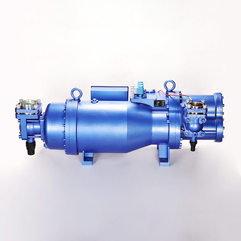
Assessing how slide valve efficiency and operational stability shift based on system temperature and pressure ratios is essential for proper system design. Different thermal applications impose unique stresses on the compression cycle. The physical properties of refrigerants change drastically depending on the suction and discharge pressures, which directly impacts how the slide valve performs when bypassing gas.
Typical load profiles in medium-temperature environments, such as standard cold storage or HVAC chillers, experience frequent demand fluctuations. Operating a medium temperature screw compressor at 50-70% slide valve capacity introduces acceptable efficiency losses. The power penalty remains manageable compared to the mechanical wear of continuous cycling. In these applications, the pressure ratio (the difference between suction and discharge pressure) is generally moderate. When the slide valve opens to bypass gas, the internal friction and the heat generated by the bypassed gas do not severely impact the overall volumetric efficiency of the machine.
Facilities running medium-temperature processes often rely on the slide valve to handle the daily peaks and valleys of production. For example, a food processing plant might need 100% capacity during the afternoon shift when product is actively being chilled, but only 60% capacity overnight to maintain room temperature. The slide valve handles this transition smoothly, keeping the suction pressure stable and preventing the compressor motor from starting and stopping multiple times an hour, which would otherwise degrade the motor contactors and mechanical couplings.
Low-temperature freezing applications present distinct challenges due to high pressure ratios. Running a low temperature screw compressor at minimum slide valve capacity below 30% can lead to excessive discharge temperatures. Volumetric efficiency drops significantly, and the risk of thermal degradation increases. In blast freezers or cold storage facilities operating at -40 degrees, the compressor must boost the low-density suction gas to a high discharge pressure. This requires a massive amount of work per unit of gas.
When the slide valve unloads a low-temperature compressor to 20% or 30%, the small volume of gas actually being compressed absorbs all the mechanical heat generated by the rotors. Because there is less mass flow to carry this heat away, the discharge temperature spikes. High discharge temperatures break down the compressor's lubricating oil, leading to carbon deposits on the rotors and premature bearing failure. Furthermore, the bypassed gas in a low-temperature system tends to heat up the incoming suction gas, further reducing the density and efficiency of the next compression cycle. For these reasons, operators must carefully limit how far a low-temperature compressor is allowed to unload mechanically.
Slide valves play a complex role in compound configurations. Modulating the low-stage and high-stage slide valves independently requires precise control logic. Balancing interstage pressures in a double stage screw compressor ensures optimal performance and prevents gas pulsation or motor overload. A double-stage system uses a booster compressor (low stage) to pull gas from the coldest evaporators and push it into an intercooler, where a high-stage compressor picks it up and pushes it to the condenser.
If the low-stage slide valve unloads too much while the high-stage remains fully loaded, the high-stage compressor will pull the interstage pressure down into a vacuum, starving itself of gas and potentially causing severe vibration. Conversely, if the high-stage unloads while the low-stage is fully loaded, the interstage pressure will skyrocket, overloading the low-stage motor and popping safety relief valves. The control system must monitor the intermediate pressure constantly and adjust both slide valves in a synchronized dance to maintain the correct mass flow through both stages of the system.
Comparing mechanical capacity reduction against electronic motor speed control highlights distinct operational philosophies. Each method offers specific advantages regarding energy consumption and upfront investment. As energy codes become stricter and electricity costs rise, facilities must evaluate whether traditional mechanical unloading is sufficient or if electronic speed control is necessary.
Analyzing the power-to-capacity curve of a slide valve reveals inherent inefficiencies. At 50% capacity, a slide valve might still consume 65-70% of full-load power due to internal friction and gas bypass inefficiencies. VFDs offer near-linear power reduction as motor speed decreases, providing superior energy performance at partial loads. When a slide valve bypasses gas, the motor is still spinning at full RPM. The rotors are still churning through the oil-gas mixture, creating parasitic drag. The gas being bypassed also creates turbulence and pressure drops within the rotor casing, all of which require motor power to overcome.
A VFD, on the other hand, slows down the actual rotation of the motor and the rotors. If the facility only needs 50% capacity, the VFD spins the compressor at 50% speed. The internal compression dynamics remain highly efficient because the rotors are fully utilizing their length, just at a slower rate. The power consumption drops almost linearly with the speed, meaning a compressor running at 50% speed via VFD will consume roughly 50% to 55% of its full-load power, resulting in massive energy savings over a year of operation.
Evaluating the upfront cost is necessary for project planning. Slide valves are standard, integrated mechanical components. High-capacity VFDs require significant electrical infrastructure, dedicated cooling, and harmonic mitigation equipment. Every industrial screw compressor comes from the factory with a slide valve mechanism built into the casing. Utilizing it requires nothing more than standard hydraulic lines and a basic PLC output. It is a robust, proven technology that requires very little specialized electrical knowledge to maintain.
Installing a VFD on a 500-horsepower compressor is a major electrical undertaking. The drive itself is physically large and generates a significant amount of heat, requiring a climate-controlled electrical room. VFDs also introduce electrical harmonics into the facility's power grid, which can interfere with sensitive electronics and require the installation of expensive line reactors or active harmonic filters. The motor itself must be rated for inverter duty to withstand the voltage spikes generated by the drive. These infrastructure requirements make VFDs a heavier initial investment.
The optimal control strategy often combines both technologies. Using a VFD for primary capacity modulation from 100% down to 50% speed maximizes efficiency. Engaging the slide valve only when demand drops below the motor's minimum safe operating speed ensures continuous operation without stalling the motor. Most compressor motors cannot be slowed down below 30% to 50% of their rated speed. Running too slow prevents the internal oil pump from generating enough pressure to lubricate the bearings, and the motor's internal cooling fan loses its effectiveness, leading to overheating.
In a hybrid system, the PLC is programmed to keep the slide valve at 100% capacity while the VFD modulates the motor speed down to its minimum safe limit (e.g., 1800 RPM down to 900 RPM). If the refrigeration load drops even further, the VFD holds the motor at 900 RPM, and the PLC begins to unload the slide valve mechanically. This strategy captures the massive energy savings of the VFD during the most common operating ranges while utilizing the slide valve to handle extreme low-load conditions without shutting the compressor off.
Control Method | Efficiency at 50% Load | Implementation Complexity | Best Application Profile |
|---|---|---|---|
Slide Valve Only | Moderate (65-70% Power Draw) | Low (Standard Factory Component) | Steady base loads, minimal daily fluctuation |
VFD Only | High (~50-55% Power Draw) | High (Requires electrical infrastructure) | Highly variable loads, strict energy targets |
Hybrid (VFD + Slide Valve) | Very High Across All Ranges | Moderate to High | Extreme load variability, low minimum load limits |
Identifying the mechanical and electrical failure points of slide valve systems prevents unexpected downtime. Proactive maintenance ensures accurate capacity modulation. A slide valve that fails to load or unload properly can cripple a facility's production capabilities or destroy the compressor motor.
Slide valves rely on hydraulic or pneumatic actuators for movement. The capacity slide valve transmitter, such as a Linear Variable Differential Transformer (LVDT) or a rotary potentiometer, communicates the exact valve position to the controller. Transmitter drift or failure leads to improper loading and severe motor strain. The hydraulic system uses the compressor's own lubricating oil to push the slide valve piston. Solenoid valves direct high-pressure oil to either the load or unload side of the piston. If these solenoids become clogged with debris or their electrical coils burn out, the slide valve will be stuck in position.
The LVDT is a delicate electronic instrument mounted on the outside of the compressor, connected to the slide valve via a mechanical rod. It translates the physical movement of the valve into a 4-20mA or 0-5V signal for the PLC. Over time, vibration and heat can cause the LVDT calibration to drift. If the LVDT tells the PLC that the valve is at 50% when it is actually at 100%, the PLC will make incorrect decisions, potentially overloading the motor or failing to meet the cooling demand.
The compressor controller dynamically adjusts the position of the slide valve relative to the motor load set point based on amperage draw. A mismatch between the reported transmitter position and the actual motor load triggers motor overcurrent trips or system instability. The primary control loop for a slide valve is usually based on suction pressure, but the secondary, overriding control loop is motor amperage. The PLC constantly monitors the current draw of the motor via a Current Transformer (CT).
If the operator sets the maximum motor load limit to 90% of Full Load Amps (FLA), the PLC will actively prevent the slide valve from loading any further once the motor hits that threshold, regardless of what the suction pressure is doing. This protects the motor during high ambient temperature days or abnormal system conditions. If the CT fails or provides an inaccurate reading, the PLC might aggressively load the slide valve, pushing the motor past its thermal limits and causing a catastrophic electrical failure.
Prolonged operation at low slide valve positions reduces refrigerant mass flow. This condition potentially causes oil logging in the evaporator or inadequate oil return to the compressor, leading to catastrophic bearing failure. Screw compressors inject large volumes of oil directly into the rotor casing to seal the gaps between the rotors, absorb the heat of compression, and lubricate the bearings. This oil mixes with the discharge gas and must be separated out in the oil separator vessel before the gas travels to the condenser.
When the slide valve is unloaded to 20%, the velocity of the discharge gas drops significantly. Low gas velocity severely impairs the efficiency of the coalescing filters inside the oil separator. More oil slips past the separator and travels out into the system piping. Without sufficient gas velocity in the suction lines to push that oil back to the compressor, the oil pools in the evaporators. The compressor eventually runs out of oil, causing metal-to-metal contact on the rotors and immediate mechanical destruction.
A diagnostic framework addresses common issues efficiently. Sticking valves often result from oil contamination or mechanical wear. Hydraulic solenoid failures and calibration errors in the control panel require immediate technical intervention to restore accurate positioning. Field technicians must follow a logical sequence when a slide valve fails to respond.
Verify the electrical signal from the PLC to the hydraulic solenoid coils. Ensure the coils are magnetizing when energized.
Check the hydraulic oil pressure. If the internal oil pump is failing or the oil filters are severely restricted, there will not be enough pressure to move the slide valve piston.
Recalibrate the LVDT transmitter. Stroke the valve fully unloaded and fully loaded manually, and reset the 0% and 100% voltage parameters in the microprocessor panel.
Inspect the mechanical linkage between the slide valve and the indicator rod. Broken roll pins or stripped threads will cause the valve to move without changing the LVDT signal.
Analyze the compressor oil for particulate contamination. Metal shavings or degraded oil sludge can physically jam the slide valve inside the rotor casing, requiring a complete compressor teardown.
Slide valves provide robust, stepless capacity control essential for preventing short-cycling in industrial screw compressors, though they introduce energy penalties at extreme low loads. Specify standard slide valve control for systems with steady loads that rarely drop below 70% capacity. Mandate a hybrid VFD and slide valve configuration for highly variable loads or strict energy compliance requirements. Carefully evaluate minimum load limits based on the specific compressor type and temperature application.
Conduct a comprehensive load profile analysis of the facility's daily and seasonal thermal demands to determine the true part-load requirements.
Consult with compressor manufacturers to calculate the exact part-load power consumption (kW/TR) for the specific application before finalizing equipment selection.
Implement a hybrid VFD and slide valve configuration if the facility experiences extreme load variations to maximize energy efficiency.
Establish a routine calibration schedule for LVDT transmitters and hydraulic solenoids to ensure accurate capacity modulation and prevent motor strain.
Monitor oil return rates closely when operating at low slide valve capacities to prevent oil logging in the system evaporators.
A: To modulate compressor capacity by bypassing a portion of the suction gas back to the inlet, reducing the volume of gas compressed without stopping the motor.
A: A capacity slide valve controls the volume of gas compressed by bypassing suction gas before compression begins, without regulating the discharge port. A Vi slide valve adjusts the internal volume ratio by modifying the location of the discharge port to match system pressures.
A: It reduces energy consumption, but not linearly. Operating at 50% capacity via slide valve typically uses more than 50% of full-load power due to bypass inefficiencies.
A: Yes. This is a common hybrid approach where the VFD handles initial capacity reduction for maximum energy efficiency, and the slide valve is used for further reduction below the motor's minimum speed threshold.
A: It is a startup sequence where the slide valve is moved to its minimum position to reduce the internal compression volume, lowering starting torque and minimizing electrical current draw on the motor.
A: The controller monitors the driver motor's electrical load and modulates the hydraulic or pneumatic solenoids to shift the slide valve, matching compressor output to the motor load set point and system demand.
A: The control system loses the actual position data of the valve, leading to incorrect loading, potential motor overload, or inability to meet the system's cooling or compression demand.


