
close
Choose Your Site
Global
Social Media
Views: 0 Author: Site Editor Publish Time: 2026-08-22 Origin: Site


In industrial refrigeration and heavy-duty gas compression, the stability of the compression cycle is fundamentally dictated by the precision of the suction pressure. Operating outside the manufacturer-specified suction pressure envelope leads to cascading mechanical failures. These breakdowns range from oil foaming and inadequate motor cooling to catastrophic rotor damage from liquid slugging or excessive discharge temperatures. Establishing the correct suction pressure range requires evaluating the specific thermal application, the refrigerant used, and the mechanical design of the compressor. This guide details how to determine optimal suction parameters, evaluate staging requirements, minimize pressure fluctuations for optimal energy consumption, and mitigate pressure-related operational risks for continuous-duty applications. We will examine practical field data, mechanical tolerances, and system controls to help you keep your equipment running smoothly and prevent unexpected downtime.
Application Dictates Range: Optimal suction pressure is not a static number; it is a dynamic range determined by the saturated suction temperature (SST) required for medium or low-temperature applications.
Efficiency and Continuous Duty: Minimizing fluctuations in suction pressure directly leads to improved volumetric efficiency, reduced energy consumption, and quieter, more dependable continuous-duty operation.
Compression Ratio Limits: Single-stage compressors lose volumetric efficiency and stability as suction pressure drops; extreme differentials require multi-stage solutions.
Thermal and Lubrication Risks: Low suction pressure starves the compressor of mass flow, leading to motor overheating and oil carryover, while excessively high suction pressure risks motor overload and liquid flood-back.
System Controls are Mandatory: Stable compression requires active regulation via slide valves, variable frequency drives (VFDs), and suction accumulators to manage transient load changes and recycle gas safely.
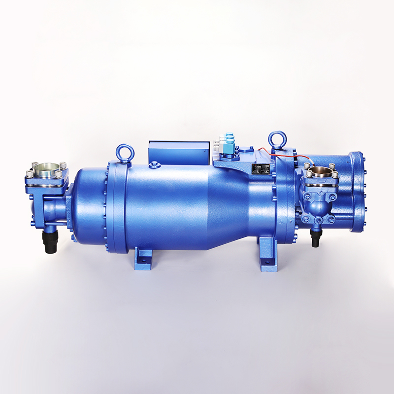
The compression cycle within a semi hermetic screw compressor begins the exact moment refrigerant gas enters the suction port. As the male and female rotors unmesh, they create a void that draws gas into the inter-lobe spaces. The volume of this space is fixed by the physical geometry of the rotors and the heavy cast-iron compressor housing. Because the physical swept volume remains constant during every rotation, the actual mass of the refrigerant drawn into the compressor depends entirely on the density of the suction gas. Suction pressure directly dictates this density.
When suction pressure remains stable and matches the design parameters of the facility, the inter-lobe spaces fill with a predictable mass of refrigerant. As the rotors continue to turn, the suction port closes. The meshing action of the lobes progressively reduces the volume of the trapped gas, driving the pressure upward until it reaches the discharge port. If the suction pressure fluctuates, the mass flow varies erratically. This inconsistency disrupts the thermodynamic balance of the entire compression cycle, causing the volumetric efficiency to drop sharply. A stable suction pressure ensures that the rotors engage with a consistent gas load. This prevents mechanical chattering, reduces bearing wear, and ensures even torque application across the drive shaft.
Achieving stability in screw compression requires meeting strict operational criteria on the factory floor. The baseline requirement is maintaining a consistent mass flow that aligns perfectly with the cooling demand of the evaporator. This consistency ensures predictable discharge temperatures. Excessive discharge heat breaks down compressor oil, carbonizes internal valves, and damages internal seals. Stable suction pressure also helps maintain the required pressure differential between the high side and low side of the system. This differential drives the internal oil circulation necessary for lubricating the rotor bearings and sealing the microscopic gaps between the meshing lobes.
System designers and field technicians must account for pressure drops across ancillary components. Industry standards dictate that the maximum allowable pressure drop across suction filters, isolation valves, and large unloading valves must remain below 0.5 bar (approximately 7 psi). Exceeding this threshold forces the compressor to work harder to draw in gas. This artificially lowers the suction pressure at the inlet and severely degrades overall efficiency. Minimizing these suction pressure fluctuations reduces mechanical vibration across the entire piping network. You get quieter operation and significantly extend the operational lifespan of the compressor in demanding environments.
To verify your system meets these success criteria, technicians should follow a strict measurement protocol:
Connect calibrated digital pressure manifolds directly to the evaporator outlet to establish the baseline suction pressure.
Attach a second set of gauges to the suction service valve located directly on the compressor body.
Record the pressure readings simultaneously while the compressor operates at 100% full load capacity.
Calculate the pressure differential between the two points. If the drop exceeds 7 psi, inspect the suction line filter drier cores for restriction.
Verify that the suction line sizing matches the manufacturer's recommendations for the specific refrigerant velocity and mass flow rate.
Medium temperature refrigeration applications operate within specific Saturated Suction Temperature (SST) ranges. You typically find these systems in cold storage facilities, meat processing plants, and large-scale HVAC chillers. Depending on the specific refrigerant utilized, a medium temperature semi hermetic screw compressor generally sees suction pressures corresponding to an SST of +20°F to +40°F (-6°C to +4°C). Operating within this relatively high suction pressure range presents unique mechanical advantages and specific engineering challenges.
The primary consideration in medium-temperature applications is motor load management. Higher suction pressures equate to higher suction gas density. This high density provides excellent cooling for the semi-hermetic motor windings. However, it also means the compressor moves a massive amount of refrigerant mass per rotation. This high mass flow requires robust motor sizing to prevent amperage overloads during peak demand periods, such as a hot pull-down after a facility washdown. Standard capacity control mechanisms, such as mechanical slide valves, modulate the compressor's output. They maintain stable suction pressure and optimize energy consumption as the thermal load on the evaporator fluctuates throughout the day.
Field engineers must pay close attention to the slide valve calibration in these medium-temperature setups. If the slide valve responds too slowly to load changes, the suction pressure will dip unnecessarily, causing the system to short-cycle. Conversely, if it responds too quickly, it can cause pressure hunting, leading to unstable expansion valve operation. Proper PID loop tuning in the central controller prevents these issues and keeps the suction pressure locked onto the setpoint.
Deep freezing, blast freezing, and pharmaceutical cold storage applications operate under vastly different thermodynamic conditions. A low temperature semi hermetic screw compressor must handle suction pressures corresponding to an SST range of -40°F to -10°F (-40°C to -23°C). At these extremely low pressures, the density of the refrigerant gas is drastically reduced. This creates a permanent condition of low mass flow.
This low mass flow introduces significant operational challenges on the mechanical side. Semi-hermetic designs rely heavily on the incoming suction gas to cool the internal electric motor. The thin, low-density gas provides very little cooling capacity. This lack of cooling puts the motor at a high risk of overheating, especially during extended run cycles. To counteract this, low-temperature screw compressors frequently require the integration of economizers.
An economizer circuit introduces a portion of subcooled liquid or intermediate-pressure vapor directly into the compression chamber midway through the compression cycle. This artificial capacity boost improves the overall efficiency of the system. More importantly, it provides critical cooling to the discharge gas and the motor windings. This ensures mechanical stability despite the exceptionally low suction pressure at the primary inlet. Technicians must regularly check the economizer expansion valve to ensure it feeds the correct amount of vapor; underfeeding leads to high discharge temperatures, while overfeeding can cause liquid injection damage to the rotors.
The stability of any compressor depends heavily on its compression ratio. You calculate this by dividing the absolute discharge pressure by the absolute suction pressure. When a single-stage compressor operates at excessively low suction pressures, the compression ratio skyrockets. Single-stage screw compressors generally operate efficiently up to a compression ratio of roughly 15:1 to 20:1, depending on the manufacturer and the specific refrigerant chemistry.
Pushing a single-stage machine beyond its design limits results in severe efficiency degradation. As the compression ratio increases, the internal leakage of high-pressure gas back to the low-pressure suction side increases exponentially. Engineers call this phenomenon blow-by. Blow-by drastically reduces volumetric efficiency because the compressor spends energy re-compressing the same gas. Furthermore, the thermal penalties are severe. High compression ratios generate immense heat, pushing discharge temperatures beyond the thermal breakdown limits of the lubricating oil. This loss of lubrication leads to rapid bearing wear, rotor expansion, and eventual catastrophic mechanical failure.
When the required suction pressure is too low for a single-stage machine to handle reliably, engineering a multi-stage solution becomes necessary. A double stage semi hermetic screw compressor is the definitive technical solution for ultra-low suction pressure and deep-freeze applications. Instead of forcing one set of rotors to handle the entire pressure lift, a double-stage system splits the total compression ratio across two separate stages housed within the same physical footprint.
This interstage pressure balancing fundamentally stabilizes the suction intake. By limiting the compression ratio of the first stage (the booster stage), the volumetric efficiency remains high. The suction pressure remains stable even under deep vacuum conditions. The discharge gas from the first stage is cooled by liquid injection or an intercooler before entering the second stage. This keeps final discharge temperatures well within safe operational limits. This architecture significantly improves the overall Coefficient of Performance (COP). You get massive long-term energy savings, reduced maintenance intervals, and unmatched dependability in continuous-duty freezing applications.
Comparison of Operational Parameters by Temperature Application
Parameter | Medium Temperature Applications | Low Temperature Applications |
|---|---|---|
Typical SST Range | +20°F to +40°F (-6°C to +4°C) | -40°F to -10°F (-40°C to -23°C) |
Suction Gas Density | High (Requires robust motor sizing) | Low (Requires supplementary motor cooling) |
Compression Ratio | Low to Moderate (Typically under 10:1) | High (Often exceeds 15:1 in single-stage) |
Economizer Requirement | Optional (Used for efficiency gains) | Mandatory (Required for cooling and capacity) |
Recommended Architecture | Standard Single-Stage Screw | Economized Single-Stage or Double-Stage Screw |
Operating a compressor with abnormally low suction pressure creates a starvation effect that cascades through the entire mechanical system. The most common causes of this condition include an undercharged refrigerant system, severely blocked suction filters, or a malfunctioning electronic expansion valve (EXV) that fails to feed the evaporator properly. When the compressor is starved of gas, the immediate mechanical impact is a dangerous spike in discharge temperatures.
Because semi-hermetic designs rely on the mass flow of suction gas to cool the internal stator and rotor windings, low suction pressure directly leads to inadequate motor cooling. If the internal thermal protection fails to trip, the motor insulation will degrade and eventually burn out. Additionally, low suction pressure results in low crankcase pressure. This pressure imbalance causes the refrigerant dissolved in the lubricating oil to boil off rapidly, leading to severe oil foaming. Foaming oil cannot be pumped effectively by the internal oil pump. This leads to oil starvation at the rotor bearings, metal-to-metal contact, and premature mechanical failure.
Conversely, allowing suction pressure to rise above the design envelope creates an overload effect that is equally destructive. High suction pressure is typically caused by an excessive thermal load on the evaporator, an overcharged refrigeration system, or failed evaporator fans that prevent proper heat exchange. High suction pressure means the compressor is ingesting highly dense gas at a massive volume.
The primary mechanical impact of high suction pressure is motor amperage overload. The compressor motor must draw excessive electrical current to physically compress the dense gas. This can easily trip breakers or damage contactors. Furthermore, the increased mass flow places immense physical stress on the rotor bearings, accelerating mechanical wear. Most critically, abnormally high suction pressure often correlates with low superheat. This drastically increases the risk of liquid refrigerant slugging. When liquid refrigerant enters the compression chamber, it washes away the hydrodynamic oil film protecting the rotors, causing severe scoring and immediate catastrophic failure.
Troubleshooting Suction Pressure Deviations
Symptom | Potential Cause | Field Action Required |
|---|---|---|
Abnormally Low Suction Pressure | Restricted suction filter drier | Measure pressure drop across filter; replace core if drop exceeds 3 psi. |
Abnormally Low Suction Pressure | Undercharged system | Check sight glass for bubbles; verify subcooling; add refrigerant as needed. |
Abnormally High Suction Pressure | Excessive thermal load (Hot pull-down) | Monitor amperage; ensure Crankcase Pressure Regulator (CPR) is functioning. |
Abnormally High Suction Pressure | Expansion valve overfeeding | Check superheat at evaporator outlet; adjust EXV parameters to close valve slightly. |
Fluctuating Suction Pressure | Hunting expansion valve | Check sensor bulb placement; insulate bulb; adjust PID loop settings. |
Maintaining stable suction pressure requires active mechanical and electronic intervention to match the compressor's pumping capacity to the real-time thermal load of the system. Mechanical slide valves are the traditional method for achieving this. A slide valve moves axially along the rotor housing, effectively bypassing a portion of the suction gas back to the inlet before it is fully compressed. This allows the compressor to operate at partial loads without stopping and starting, thereby stabilizing the suction pressure. However, running compressors unloaded for extended periods via slide valves can negatively impact oil return and overall isentropic efficiency.
Variable Frequency Drives (VFDs) represent the modern standard for precision pressure regulation. A VFD alters the electrical frequency supplied to the compressor motor, speeding it up or slowing it down to perfectly match the system load. By continuously modulating the rotor speed, a VFD eliminates the drastic suction pressure fluctuations associated with traditional stepped capacity control. This continuous modulation results in significantly reduced energy consumption, tighter temperature control, and less mechanical wear on the drive components. When installing a VFD, technicians must ensure the minimum speed setting still provides enough mass flow to cool the motor and drive the internal oil pump.
Beyond capacity control, specific piping components protect the compressor from transient pressure spikes. Crankcase Pressure Regulators (CPR) are critical mechanical valves installed in the suction line just before the compressor inlet. During a hot pull-down, when the evaporator pressure is exceptionally high, the CPR throttles the flow of gas. This ensures the suction pressure at the compressor never exceeds the maximum allowable limit, preventing motor overload and nuisance breaker trips.
Evaporator Pressure Regulators (EPR) serve a different function. They maintain a minimum pressure within the evaporator coil to prevent localized freezing, which indirectly stabilizes the gas flow returning to the compressor. Finally, properly sized suction accumulators are mandatory in systems prone to load fluctuations. The accumulator acts as a physical buffer in the suction line. It traps any liquid refrigerant that escapes the evaporator and allows it to boil off safely into a vapor before it can reach the compressor. This dampens sudden pressure transients and completely eliminates the risk of liquid slugging.
Stable screw compression requires strictly maintaining suction pressure within the compressor’s specific operating envelope. Deviations directly compromise volumetric efficiency, hydrodynamic lubrication, energy consumption, and the physical lifespan of the motor. When suction pressure fluctuates wildly, the entire refrigeration cycle becomes unpredictable and prone to mechanical breakdown. Equipment selection must be driven entirely by the required Saturated Suction Temperature. Medium temperature applications generally allow for standard single-stage models equipped with robust capacity controls. Low temperature requirements necessitate the advanced engineering of economized single-stage or dedicated double-stage architectures to manage the extreme compression ratios.
To ensure long-term stability and protect your equipment, execute the following steps:
Consult compressor performance software to map the exact suction and discharge envelopes for the chosen refrigerant under peak load conditions.
Audit existing suction line piping to ensure pressure drops across filters and valves remain strictly below 0.5 bar.
Implement Variable Frequency Drives (VFDs) to modulate compressor speed, eliminating the pressure spikes associated with traditional on/off cycling.
Install and calibrate Crankcase Pressure Regulators (CPRs) to protect the semi-hermetic motor from amperage overloads during high-load pull-downs.
Schedule quarterly oil analysis to detect early signs of bearing wear caused by transient suction pressure drops.
A: Low suction pressure reduces the mass flow of refrigerant gas, which is required to cool the internal motor. This leads to motor overheating, excessively high discharge temperatures, and potential oil circulation failures as the crankcase pressure drops below the minimum threshold required to drive the oil pump.
A: The compression ratio is calculated by dividing absolute discharge pressure by absolute suction pressure. As suction pressure drops, the compression ratio increases exponentially. High compression ratios reduce volumetric efficiency, increase discharge temperatures, and place immense mechanical stress on the rotor bearings.
A: In low-temperature applications, the required suction pressure is very low. A double-stage compressor splits the high compression ratio across two sets of rotors. This keeps discharge temperatures manageable, maintains stable volumetric efficiency, and significantly reduces energy consumption compared to a single-stage unit.
A: While specific system designs vary, industry best practices generally recommend keeping suction line and unloading valve pressure drops below 7 psi (0.5 bar). Exceeding this limit starves the compressor, causing unnecessary capacity loss and severe efficiency degradation.
A: Yes. By precisely modulating the compressor motor speed to match the real-time cooling load, a VFD prevents the drastic suction pressure fluctuations associated with traditional on/off or stepped capacity control. This leads to quieter, more stable, and highly efficient operation.
A: A CPR valve is installed in the suction line to prevent the suction pressure at the compressor inlet from rising above a predetermined safe limit. This mechanical throttling protects the semi-hermetic motor from electrical overloading during high-load conditions, such as a hot pull-down.


