
close
Choose Your Site
Global
Social Media
Views: 0 Author: Site Editor Publish Time: 2026-08-06 Origin: Site


Selecting industrial cooling equipment based on nominal capacity rather than specific thermodynamic operating conditions guarantees systemic inefficiency, premature mechanical failure, or catastrophic system downtime. Engineers and facility managers frequently misalign system load requirements with manufacturer performance data. This occurs when the exact duty point—the precise intersection of pressures, temperatures, and refrigerant characteristics—is poorly defined or misunderstood during the procurement phase.
Accurate equipment specification requires translating environmental and process loads into a strict set of data parameters. This guide deconstructs the exact data required to define a refrigeration compressor duty point, how these metrics influence technology selection, and how to evaluate manufacturer technical data for reliable system design.
A refrigeration compressor duty point is a specific thermodynamic operating condition defined primarily by evaporating temperature, condensing temperature, superheat, and subcooling—not a generalized capacity rating.
Accurate duty point data is the only reliable baseline for comparing the Coefficient of Performance (COP) and mass flow rates across different compressor architectures.
The thermodynamic duty point must be distinguished from the physical nameplate data (such as displacement, RLA, and LRA), though they are closely interlinked during system commissioning.
Failing to account for ambient temperature extremes and part-load variances will push the compressor outside its safe operating envelope, regardless of the initial duty point calculation.
Matching the calculated duty point to the correct technology profile (e.g., scroll, screw, or semi-hermetic) minimizes lifecycle energy costs and mitigates implementation risks.
A thermodynamic duty point represents the exact operating condition used for capacity and power evaluation. It differs entirely from nominal capacity, which serves as a standardized, theoretical rating for marketing and baseline comparison. Nominal ratings assume ideal laboratory conditions. Real-world applications demand precise calculations based on the actual thermal load, ambient environment, and system piping design. Relying solely on nominal capacity often leads to undersized or oversized equipment, causing erratic temperature control and excessive energy consumption. You must calculate the exact requirements based on the specific application.
When you evaluate a system, you are looking at the exact pressure and temperature coordinates where the machine operates. This is not a rough estimate. It is a precise mathematical intersection that dictates how much refrigerant mass the machine must move to satisfy the load. If you get this wrong, the entire system suffers from poor performance and shortened lifespan.
Industry professionals sometimes confuse duty points with duty cycles. An air compressor's duty cycle refers to operational run-time percentages, dictating how long the machine can run continuously before requiring a cooldown period. In contrast, a refrigeration duty point refers strictly to the specific pressure-temperature coordinates where the compressor performs its mechanical work. It defines the thermodynamic state of the refrigerant entering and exiting the compressor, dictating the required mass flow rate to satisfy the cooling load.
Understanding this distinction is critical for field technicians and design engineers alike. A machine might have a 100% duty cycle, meaning it can run continuously, but if it is operating at the wrong duty point, it will still fail prematurely due to thermal overload or poor oil return.
Standard rating conditions, such as EN 12900 and AHRI 540, establish uniform testing parameters for compressor manufacturers. These standards allow engineers to compare different brands on a level playing field. However, real-world duty points rarely align perfectly with laboratory standards. A facility operating in a desert climate will experience significantly higher condensing temperatures than the AHRI 540 baseline. Engineers must interpolate manufacturer data to match actual site conditions rather than accepting standard rating tables at face value.
Standard | Evaporating Temp | Condensing Temp | Application Focus |
|---|---|---|---|
AHRI 540 | Varies by application | Standardized baselines | North American commercial refrigeration |
EN 12900 | Standardized points | Standardized points | European performance rating |
Physical compressor label data provides fixed hardware specifications. Displacement indicates the physical volume swept by the pistons or rotors per revolution. Locked Rotor Amps (LRA) and Rated Load Amps (RLA) define electrical limits. The certified oil charge dictates lubrication requirements. While this nameplate data is critical for electrical sizing and maintenance, it remains static. The thermodynamic duty point is dynamic, fluctuating with environmental changes and process loads. Understanding the relationship between fixed physical limits and dynamic thermodynamic requirements is essential for successful system commissioning.
Saturated Suction Temperature (SST) acts as the primary driver of volumetric efficiency. It represents the temperature at which the refrigerant boils in the evaporator coil. As SST drops, the specific volume of the suction gas increases, meaning the compressor moves less refrigerant mass per stroke. Target room temperature and the evaporator Temperature Difference (TD) dictate this metric. A lower TD requires a larger evaporator coil but allows for a higher SST, improving overall compressor efficiency and reducing power consumption.
In the field, you will often see systems struggling because the SST was calculated incorrectly during the design phase. If the evaporator is undersized, the SST must drop to meet the room temperature requirement, which starves the compressor and forces it to work harder.
Saturated Condensing Temperature (SCT) correlates directly to ambient environmental conditions. It represents the temperature at which the refrigerant vapor condenses back into a liquid. Higher ambient temperatures force the SCT upward, increasing the discharge pressure. This elevated pressure increases the compression ratio, which exponentially increases total power consumption and reduces cooling capacity. Managing SCT through proper condenser sizing and placement is critical for maintaining an efficient duty point.
Return gas temperature defines the thermal state of the refrigerant vapor entering the compressor. Superheat ensures the refrigerant is entirely vaporized, preventing liquid slugging that can destroy compressor valves and pistons. However, engineers must balance this requirement. Excessive superheat reduces gas density, lowering mass flow and capacity. It also elevates discharge temperatures, potentially causing oil breakdown. Optimal system design maintains sufficient superheat to protect the mechanics while minimizing it to ensure adequate motor cooling and high volumetric efficiency.
Subcooling occurs when the liquid refrigerant is cooled below its saturation temperature at the condenser exit. This process increases the net refrigeration effect in the evaporator without requiring additional compressor power input. Internal subcooling happens naturally within the condenser coil. External subcooling utilizes dedicated heat exchangers or economizers. Accurately defining the subcooling value at the duty point is necessary to calculate the true enthalpy difference and the resulting mass flow requirement.
Measure the liquid line temperature at the condenser outlet.
Determine the saturation temperature from the discharge pressure.
Subtract the liquid line temperature from the saturation temperature to find the subcooling value.
Complex industrial systems often utilize multi-stage compression, such as two-stage or cascade booster systems using natural refrigerants like CO2 or ammonia. In these applications, the duty point calculation becomes more intricate. Intermediate pressures, desuperheating methods, and economizer injection directly modify the single-stage duty point equation. Engineers must calculate the intermediate pressure that balances the compression ratios across both stages to optimize power consumption and prevent excessive discharge temperatures.
The specific thermodynamic properties of the chosen refrigerant interact heavily with operating temperatures to determine the required mass flow rate. High-pressure refrigerants like CO2 require significantly lower volumetric flow rates compared to propane or ammonia for the same cooling capacity. The duty point must explicitly define the refrigerant type, as the enthalpy curve dictates how many pounds per hour or kilograms per second the compressor must move to satisfy the thermal load.
The industry-standard mathematical method for calculating performance mapping relies on a 10-coefficient polynomial equation. Manufacturers provide these coefficients based on extensive laboratory testing. By inputting the specific SST and SCT of the desired duty point into this equation, engineers can calculate precise mass flow rates, compressor power input, current draw, and cooling capacity. This mathematical model replaces outdated performance curves, offering exact data points for customized system design and energy modeling.
Thermodynamic equations allow engineers to estimate compressor shaft power and condenser heat rejection duty. The power input depends on the mass flow rate and the enthalpy difference between the suction and discharge states. The condenser duty equals the sum of the cooling capacity and the compressor power input. Accurately calculating these values at the specific duty point ensures that all secondary components, including contactors, wiring, and heat exchangers, are correctly sized for the application.
Selecting the correct compressor architecture requires matching the defined duty point to the specific operating envelope and motor cooling design of the equipment. Suction gas-cooled motors rely on the returning refrigerant to prevent overheating, making them sensitive to high superheat conditions. Air or water-cooled motors offer more flexibility in high-temperature applications. The success criteria depend on aligning the thermodynamic demands with the mechanical strengths of the chosen technology.
A scroll refrigeration compressor excels in medium to high-temperature duty points. These units utilize fixed volumetric ratios and compliance mechanisms that handle liquid handling better than rigid designs. Their efficiency sweet spots make them ideal for commercial retail, supermarket racks, and light industrial applications. However, their fixed built-in volume ratio means efficiency drops significantly if the actual operating pressures deviate far from the design parameters.
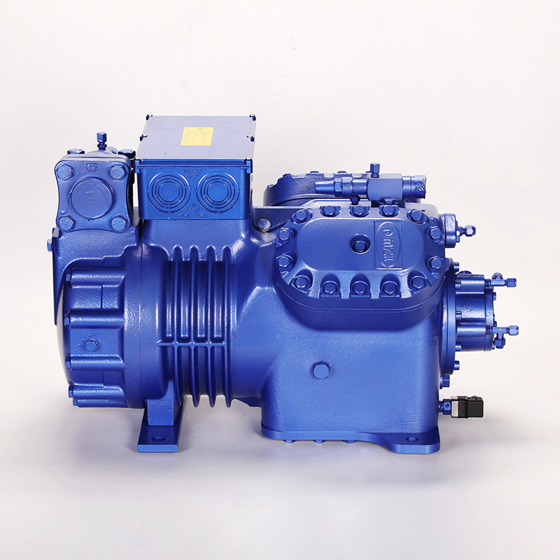
Applications requiring broad operating envelopes, variable loads, and field serviceability benefit greatly from a semi hermetic refrigeration compressor. These machines offer immense mechanical robustness when duty points fluctuate due to seasonal ambient changes or shifting process loads. The ability to rebuild valve plates and replace motors on-site reduces long-term downtime in critical industrial facilities. Their versatile design allows for capacity modulation through cylinder unloading or variable frequency drives.
Large-capacity, heavy industrial duty points, such as those found in cold storage and food processing, require a screw refrigeration compressor. These units handle massive volumes of refrigerant gas efficiently. They utilize slide valves for precise capacity control, allowing the machine to maintain high efficiency at specific part-load duty points. Screw compressors are particularly effective in applications with stable, continuous loads and high compression ratios.
Low-capacity, cost-sensitive commercial and domestic applications typically utilize fully hermetic reciprocating designs. While cost-effective, their internal motor winding temperature limits strictly restrict the allowable operating envelope compared to open or semi-hermetic designs. If the duty point shifts into high compression ratios or low suction pressures, the lack of adequate motor cooling will cause rapid thermal overload and premature failure.
Reading manufacturer performance tables or selection software requires focusing on the exact duty point rather than peak ratings. Engineers must calculate the true Coefficient of Performance (COP) and Energy Efficiency Ratio (EER) based on specific thermodynamic data. High cooling capacity is useless if it requires disproportionate power input. Evaluating the ratio of useful cooling to electrical consumption at the precise operating conditions ensures the system meets energy compliance standards and operational budgets.
The compressor duty point must harmonize perfectly with the condenser coil capacity and fan performance within a packaged refrigeration condensing unit. If the condensing unit is undersized, it will bottleneck system performance, forcing the SCT higher and pushing the compressor out of its safe operating zone. The total heat of rejection—which includes both the cooling load and the heat of compression—must be matched to the condensing unit's capacity at the peak ambient design temperature.
Plotting the duty point on a manufacturer's application envelope reveals the safety margins of the design. The envelope defines the acceptable boundaries of evaporating and condensing temperatures. Identifying boundary risks involves checking for high discharge temperatures at the top of the envelope, low suction pressures at the left edge, and motor overload zones at the bottom right. Operating too close to these boundaries requires mitigation strategies like liquid injection or demand cooling.
Spikes in summer ambient temperatures alter the condensing pressure, potentially pushing the compressor out of its envelope. This risk requires designing for peak ambient duty points and utilizing physical control mechanisms to stabilize SCT. Condenser flooding valves, head pressure control valves, and variable-speed fan controls help maintain stable discharge pressures during winter, while ensuring the condenser can reject sufficient heat during extreme summer heatwaves.
Operating continuously at off-design duty points leads to poor oil return, localized motor overheating, and hunting expansion valves. Industrial loads rarely remain static. Implementing VFDs or mechanical capacity modulation maintains efficiency across a spectrum of secondary duty points. By matching the compressor speed to the actual thermal load, the system avoids short-cycling and maintains stable suction pressures, protecting the mechanical integrity of the equipment.
Fouled condenser coils, iced evaporators, or degraded refrigerant charges artificially shift the compressor's operating pressures away from the commissioned duty point. This degradation forces the compressor to work harder, consuming more power for less cooling effect. Baseline duty point commissioning provides a reference for future performance. Continuous predictive maintenance monitoring and regular sensor calibration are required to identify these shifts before they cause mechanical failure.
Lock in your Saturated Suction Temperature, Saturated Condensing Temperature, superheat, and subcooling data before comparing compressor brands.
Utilize manufacturer-specific selection software to model the exact duty point under peak and part-load conditions.
Request comprehensive technical data sheets, including the AHRI 10-coefficient table, for accurate energy modeling.
Consult with application engineers to verify envelope limits and ensure all secondary components are sized correctly.
A: A duty cycle refers to the percentage of time a machine runs continuously versus resting. A duty point is the specific thermodynamic condition—defined by pressures, temperatures, and refrigerant type—where the compressor operates to meet a specific cooling load.
A: High ambient temperatures reduce the condenser's ability to reject heat, forcing the Saturated Condensing Temperature (SCT) and discharge pressure to rise. This increases the compression ratio, demanding more power and reducing the compressor's cooling capacity.
A: Return gas temperature determines the density of the refrigerant entering the compressor and provides necessary motor cooling. Too high, and the motor may overheat while capacity drops. Too low, and liquid refrigerant may enter the cylinders, causing mechanical damage.
A: It can operate within its defined application envelope, but running outside the specific design duty point reduces efficiency. Operating completely outside the manufacturer's envelope risks motor burnout, oil breakdown, or mechanical failure due to extreme pressures or temperatures.
A: Mass flow rate is calculated by dividing the total required cooling capacity by the net refrigeration effect (the enthalpy difference between the refrigerant entering the evaporator and leaving it). This dictates how much refrigerant the compressor must move.


