
close
Choose Your Site
Global
Social Media
Views: 0 Author: Site Editor Publish Time: 2026-08-18 Origin: Site


Industrial refrigeration thermal loads rarely remain static. Ambient temperatures shift, production cycles peak, and product volumes change daily. When cooling capacity fails to match system demand, facilities face severe mechanical and financial consequences. Compressors short-cycle aggressively, slamming internal components and spiking energy consumption. Drive components suffer accelerated mechanical wear from constant starting torque. Solving this requires precise load matching. Multi-cylinder reciprocating systems offer a proven mechanical architecture to handle these fluctuations. Specifically, a 6 cylinder refrigeration compressor allows for accurate, stepped capacity reduction. It achieves this without relying entirely on external variable frequency drives. By unloading cylinders in pairs, the system drops capacity to match the exact evaporator load, stabilizing suction pressures and protecting the motor.
Stepped Capacity Reduction: Unloading two cylinders in a six-cylinder configuration yields a precise 33% reduction in full-load capacity, allowing for 100%, 66%, and 33% operational stages.
Mechanical Unloading Mechanisms: Suction valve unloaders are mechanisms designed to prevent gas compression within a compressor cylinder by physically holding the suction valves open during low-load periods.
System Longevity: Effective load management mitigates the dynamic loading and fatigue stress typically inflicted on cylinder valves during continuous on/off cycling, ensuring valves operate reliably at each cycle.
Application Versatility: When configured as a low temperature piston compressor, multi-cylinder unloading maintains critical temperature setpoints while managing the specific oil-return challenges of partial-load operation.
Variable load management requires a specific baseline outcome. The system must reduce refrigerant mass flow to match the current evaporator load. It must accomplish this while maintaining stable suction pressure and acceptable discharge temperatures. If the compressor pulls too much vapor from the evaporator, suction pressure drops rapidly. Low suction pressure causes coil freezing, oil foaming in the crankcase, and severe system instability. A high capacity piston compressor uses mechanical intervention to prevent this pressure drop, ensuring the system operates within its designed envelope.
Suction valve unloading represents the most common and reliable method for capacity control in multi-cylinder machines. The process relies on manipulating the internal valve mechanics to stop compression in specific cylinders. When the control system detects a drop in cooling demand, it initiates a mechanical sequence to unload a bank of cylinders.
The programmable logic controller (PLC) or mechanical pressure switch detects a drop in suction pressure, indicating reduced evaporator load.
An electrical signal energizes the solenoid coil on the pilot valve located on the cylinder head.
The pilot valve opens, directing high-pressure discharge gas (or in some designs, high-pressure oil) into the unloader assembly.
This pressure forces an unloader piston downward against a heavy return spring.
The unloader piston pushes lifting pins against the suction valve reeds, physically holding them away from the valve plate.
As the main compressor piston moves up and down, refrigerant vapor simply pulses in and out of the open suction port without being compressed.
Because no compression occurs, the cylinder performs no work on the gas. This drastically reduces the electrical power consumed by the motor. The piston still moves, so mechanical friction remains, but the heavy lifting of gas compression stops entirely for that specific cylinder bank.
Clearance pockets offer a different approach to capacity reduction. This method artificially increases the internal volume of the cylinder at the top of the piston stroke. A valve opens a chamber located in the cylinder head. During the compression stroke, refrigerant gas fills this extra pocket. On the downstroke, the trapped high-pressure gas expands back into the main cylinder.
This expansion reduces the volumetric efficiency of the cylinder. Less new suction gas can enter, effectively lowering the capacity. While clearance pockets work well for controlling a single large reciprocating compressor, they add significant bulk. They are generally less efficient and more mechanically cumbersome when applied to modern, compact multi-cylinder configurations. They also generate excess heat, as the same gas is repeatedly compressed and expanded without leaving the cylinder.
Engineers map the physical action of unloading directly to operational outcomes. The primary metric is the proportional drop in electrical power consumption relative to the reduction in volumetric displacement. When a cylinder unloads, the motor no longer expends energy compressing gas in that specific bore. Holding suction valves open provides a clean, immediate reduction in mass flow without destabilizing the broader refrigeration cycle. This mechanical intervention prevents the motor from overheating while keeping the crankshaft spinning, which maintains basic oil pump operation and system circulation.
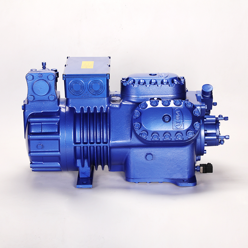
The specific staging of a multi-cylinder unit dictates its ability to track varying thermal loads. A six cylinder refrigeration compressor provides a distinct mathematical advantage over other configurations. Cylinders are typically grouped and unloaded in pairs, often referred to as banks. This pairing maintains mechanical balance across the crankshaft, preventing severe vibration that could fracture piping or damage motor bearings.
The operational states follow a precise sequence. When peak demand occurs, all six cylinders remain active, delivering 100% capacity. As the load decreases, the control system unloads the first bank. Four cylinders remain active, dropping the capacity to 66%. If the load drops further, the system unloads a second bank. Two cylinders remain active, reducing the full-load capacity by exactly 33%. This granular, three-step framework allows the refrigeration plant to match moderate and low-load conditions without aggressive short-cycling.
Evaluating a six cylinder semi hermetic compressor against other piston models reveals clear practical benefits. A 4-cylinder compressor only offers two capacity steps: 100% and 50%. A 50% jump often proves too large for precise temperature control, leading to temperature swings in the conditioned space. An 8-cylinder compressor provides 25% steps, offering excellent granularity. However, 8-cylinder machines require a massive physical footprint. They introduce more moving parts, increasing the potential points of failure. The 6-cylinder unit strikes a highly practical balance. It delivers tight step control without the excessive mechanical complexity of larger V-8 or W-12 configurations.
Scroll compressors utilize an orbiting scroll driven by a crankshaft. They handle varying loads efficiently and tolerate liquid slugging better than most reciprocating designs. Despite these advantages, piston compressors maintain dominance in heavy industrial applications due to superior field-serviceability and raw volumetric output.
When a scroll compressor suffers internal damage, technicians must typically replace the entire unit. This requires cutting pipes, recovering large volumes of refrigerant, and heavy rigging. In contrast, piston compressors feature field-rebuildable components. If a valve fails, a technician can isolate the compressor, remove the cylinder head, and execute a quick-change suction valve replacement in a few hours. This maintainability proves critical for facilities that cannot tolerate extended downtime.
Compressor Architecture Comparison
Configuration | Available Capacity Steps | Mechanical Complexity | Field Serviceability |
|---|---|---|---|
4-Cylinder Piston | 100%, 50% | Low | Excellent |
6-Cylinder Piston | 100%, 66%, 33% | Moderate | Excellent |
8-Cylinder Piston | 100%, 75%, 50%, 25% | High | Good |
Industrial Scroll | Variable (Digital/VFD) | Low (Internal) | Poor (Requires full replacement) |
Operating refrigeration equipment at partial capacity introduces unique physical stresses. A low temperature piston compressor faces severe challenges when running unloaded for extended periods. Understanding these physical tolls is necessary for designing resilient systems that survive harsh industrial environments.
Cyclic operation destroys mechanical components. Cylinder valves open and close thousands of times per minute. They slam against valve seats repeatedly. Because cylinder valves should be operated at each cycle under normal conditions, they experience considerable dynamic loading and fatigue stress. Continuous on/off cycling of the entire compressor amplifies this stress, leading to premature metal fatigue and catastrophic valve failure.
Capacity control mechanisms mitigate this damage. By keeping the compressor running and simply holding the suction valves open, the system eliminates the violent startup torque and pressure equalization shocks associated with turning the motor on and off. The unloading mechanisms themselves must be robust. They must actuate reliably under high pressure differentials without suffering premature mechanical failure. The lifting pins and unloader pistons must resist wear from constant vibration.
Motor cooling presents a critical challenge. Semi-hermetic compressors rely on cold suction gas flowing over the internal stator windings to dissipate electrical heat. When a six-cylinder unit operates at 33% capacity, the mass flow of suction gas drops by 67%. The motor still generates significant heat while driving the crankshaft and the two active pistons. The ratio of cooling gas to generated heat skews dangerously.
If the system runs at this lowest capacity step for too long, the reduced gas flow fails to cool the motor adequately. Internal temperatures spike, degrading the motor insulation and risking a grounded winding. Engineers must account for this by integrating supplemental cooling strategies. Demand cooling injection systems spray atomized liquid refrigerant directly into the suction cavity to artificially cool the windings when discharge temperatures exceed safe limits.
Oil return creates another severe operational hurdle. Refrigerant vapor carries lubricating oil through the system piping. High vapor velocities push the oil up vertical risers and return it to the compressor crankcase. Lower refrigerant velocities at partial loads fail to carry the oil. The oil drops out of suspension and pools in the evaporator or suction lines. The compressor eventually runs dry, leading to bearing seizure. Piping design must account for the lowest capacity step. Double suction risers and high-efficiency oil separators are mandatory to ensure proper lubrication during 33% operation.
Partial Load Troubleshooting
Symptom | Potential Cause at Partial Load | Field Correction |
|---|---|---|
High Motor Temperature | Inadequate suction gas flow at 33% capacity. | Verify demand cooling injection operation; check superheat. |
Low Oil Level in Crankcase | Low vapor velocity in suction risers trapping oil. | Inspect P-traps; verify double suction riser sizing. |
Rapid Staging (Hunting) | Control deadbands set too tight. | Widen pressure differentials in the PLC; add time delays. |
Compressor Will Not Load | Unloader solenoid failed open or manual stem engaged. | Check coil voltage; reset manual override stem to auto. |
Selecting the correct load management approach requires evaluating upfront costs, operational complexity, and long-term reliability. Facility managers must weigh conceptual trade-offs before finalizing a system architecture. A poorly specified control strategy leads to erratic temperatures and premature equipment failure.
Mechanical suction valve unloaders offer rugged simplicity. They utilize basic solenoid valves and pressure differentials. They are field-tested, highly reliable, and relatively inexpensive to implement. Troubleshooting requires basic mechanical knowledge and standard refrigeration gauges. If a solenoid fails, a technician can replace the coil in minutes without disrupting the entire electrical panel.
Variable Frequency Drives (VFDs) provide infinite capacity variability. A VFD alters the electrical frequency supplied to the motor, slowing down or speeding up the crankshaft rotation. This allows the compressor to match the load perfectly, running at 42% or 58% capacity as needed. However, VFDs introduce high electrical complexity. They can generate harmonic distortion that affects other electronic equipment in the facility. They require shielded cables, line reactors, and a significantly higher initial capital investment. Furthermore, slowing the motor rotation too much exacerbates the oil return and motor cooling issues mentioned earlier. If the crankshaft spins too slowly, the internal oil pump cannot generate enough pressure to lubricate the rod bearings.
Modern industrial refrigeration often utilizes a hybrid approach. This strategy combines a VFD with mechanical unloading on a multi-cylinder compressor. The control system uses the VFD for fine-tuning capacity between the mechanical steps. For example, the compressor operates all six cylinders and uses the VFD to modulate between 100% and 66% capacity. If the load drops further, the system unloads a cylinder bank and ramps the VFD back up to full speed. This hybrid method achieves near-perfect load matching while keeping motor speeds high enough to ensure proper oil return and cooling.
Analyze the facility's historical thermal load data to identify minimum and maximum cooling demands.
Determine the required temperature tolerance for the conditioned space or process fluid.
Evaluate the existing electrical infrastructure for VFD compatibility, including harmonic mitigation.
Assess the piping layout to confirm oil return velocities at the lowest projected capacity step.
Select the control strategy (mechanical, VFD, or hybrid) that meets the load profile without compromising compressor lubrication.
Stepped capacity control directly aids facilities in meeting stringent energy efficiency regulations. Standards set by the Department of Energy (DOE) and EcoDesign directives focus heavily on part-load performance. Refrigeration plants rarely operate at peak design conditions. They spend the vast majority of their operational life at partial loads.
Improving the Integrated Part Load Value (IPLV) is essential for compliance. Mechanical unloading drastically reduces power consumption during these extended part-load periods. A properly staged six-cylinder system scales efficiently, ensuring the facility remains compliant with evolving energy codes while minimizing daily electrical draw. By matching the mass flow to the exact load, the system avoids wasting energy on unnecessary gas compression.
Deploying multi-cylinder unloading systems introduces specific operational risks. Identifying these risks during the design phase allows engineers to implement effective mitigation strategies, ensuring long-term reliability and preventing catastrophic downtime.
Continuous capacity modulation forces unloader mechanisms to actuate frequently. This high cycle rate inflicts fatigue stress on the pilot valves, lifting pins, and springs. Over time, these components wear out. A failed unloader may stick in the open position, permanently reducing compressor capacity, or stick closed, causing the system to overcool and short-cycle.
Mitigation requires specifying high-cycle solenoid valves designed for continuous duty. Facility managers must mandate strict preventative maintenance schedules. Unloader assemblies should be inspected annually and rebuilt during major compressor overhauls to prevent unexpected failures. Technicians must check the lifting pins for mushrooming or excessive wear during routine valve plate inspections.
Improperly tuned control systems cause a phenomenon known as "hunting." If the staging deadbands are too narrow, the system rapidly loads and unloads the cylinders in response to minor pressure fluctuations. This rapid cycling destroys contactors, burns out solenoids, and shatters valve plates. The mechanical shock of constant loading and unloading stresses the crankshaft and connecting rods.
Mitigation involves implementing advanced PLC controls. Programmers must establish appropriate time delays between staging events. They must widen the pressure differentials (deadbands) to stabilize the system. An anti-short-cycle timer ensures that once a cylinder bank unloads, it remains unloaded for a minimum duration before reloading. This prevents the system from reacting to momentary pressure spikes caused by sudden valve movements elsewhere in the plant.
Compressor pilot valves feature a manual handle or stem on the side of the valve body. This handle manually forces the lifting mechanism to engage or disengage, regardless of the electrical signal from the control system. This feature is highly useful for diagnostic testing. It allows technicians to verify mechanical operation without using the PLC. It also facilitates quick suction valve changeovers and permits emergency operation if a solenoid coil burns out.
The risk occurs when technicians forget to reset the handle. If left in the manual unload position, the compressor cannot respond to peak cooling demands, leading to rising space temperatures and potential product loss. Mitigation relies on strict standard operating procedures (SOPs). Maintenance protocols must dictate that all manual overrides are physically verified and reset to automatic mode before a technician leaves the mechanical room. Visual indicators or lockout tags can help enforce this requirement.
Audit your facility's load profile to determine the frequency and duration of partial-load conditions.
Inspect existing suction and liquid piping to verify oil return velocities meet manufacturer specifications at 33% capacity.
Establish a strict preventative maintenance schedule to rebuild unloader assemblies and inspect lifting pins annually.
Program PLC deadbands and anti-short-cycle timers to prevent rapid staging and mechanical hunting.
A: Cylinder unloading works by utilizing pilot valves to direct pressure to a lifting mechanism. This mechanism physically holds the suction valves open in pairs. Gas pulses in and out of the cylinder without being compressed. This prevents gas compression, reduces capacity in 33% increments, and manages dynamic loading on the internal components.
A: Unloading two cylinders reduces the active displacement of the machine by exactly one-third. Because the cylinders are grouped in three banks of two, dropping one bank reduces the full-load capacity by exactly 33%, leaving the compressor operating at 66% capacity.
A: Yes, combining mechanical unloading with a Variable Frequency Drive provides highly precise capacity control. The VFD handles fine modulation between the mechanical steps. However, technicians must strictly monitor motor cooling limits and oil return at low Hertz frequencies to prevent internal damage.
A: While scroll compressors are reliable for varying loads, piston compressors offer larger total capacities and superior field serviceability. Technicians can rebuild components like quick-change suction valves on-site. Piston units also feature robust mechanical unloading mechanisms perfectly suited for heavy, continuous industrial environments.
A: The primary risks involve thermal and lubrication failures. Reduced suction gas flow causes inadequate motor cooling, potentially overheating the stator windings. Additionally, low refrigerant velocities in the piping prevent proper oil return, which can lead to the compressor crankcase running dry and seizing the bearings.
A: The manual handle allows technicians to manually load or unload the compressor cylinders without relying on the automated control system. It is used primarily for diagnostic testing, facilitating quick maintenance changeovers, or forcing emergency operation if an electrical solenoid coil fails.


