
close
Choose Your Site
Global
Social Media
Views: 0 Author: Site Editor Publish Time: 2026-08-23 Origin: Site


Industrial deep freezing operates within a strict thermodynamic threshold, typically spanning -30°C to -60°C. Forcing standard refrigeration equipment to meet these extreme parameters incurs a massive energy penalty. Single-stage compression struggles at high pressure ratios. This results in a severe drop in volumetric efficiency, dangerous spikes in discharge temperatures, and accelerated mechanical wear. When evaporation temperatures plummet, the physical limits of standard compressors become a bottleneck for facility operations.
The double stage screw compressor serves as the engineered response to these high-lift applications. By dividing the compression workload across two distinct phases, this architecture mitigates the thermal and mechanical stresses that destroy conventional equipment. This technical evaluation covers its mechanics, system integration, and operational advantages compared to alternative refrigeration strategies. Facility operators and refrigeration engineers must understand these dynamics to maintain reliable, continuous deep freezing capabilities.
Efficiency at High Pressure Ratios: Splitting the compression cycle into two stages drastically reduces the pressure differential per stage, maintaining high volumetric efficiency in deep freeze applications.
Thermal Management: Interstage cooling (often via liquid injection or an economizer) prevents the lubricant and refrigerant from degrading under the high heat of extreme compression.
System Complexity vs. Payback: While a double stage screw compressor introduces additional rotors, iron casing, and componentry, the energy savings in low-temperature operations typically offset the higher initial capital expenditure.
Architectural Flexibility: Modern deep freeze facilities must evaluate specific configurations, such as the semi hermetic double stage screw compressor, to balance footprint, leak prevention, and maintenance accessibility.
Deep freezing applications, including blast freezers and pharmaceutical cold storage, demand exceptionally low evaporation temperatures. Meanwhile, condensing temperatures remain tied to ambient environmental conditions. This vast temperature differential creates a massive pressure gap that the refrigeration system must bridge. Single-stage compressors face physical operational limits when attempting to clear this gap in a single stroke.
High compression ratios severely degrade the performance of single-stage compressors. The compression ratio represents the difference between suction pressure and discharge pressure. When this ratio exceeds 10:1, the mechanical demands on the compressor multiply. The motor draws excessive current, internal components face extreme stress, and the overall efficiency of the refrigeration cycle collapses. Single-stage units simply cannot move enough refrigerant mass at these elevated ratios to maintain stable deep freezing temperatures. The physical geometry of the rotors cannot trap and compress the low-density gas effectively without massive energy input.
Excessive discharge heat introduces severe physical risks to the system. As the compression ratio climbs, the temperature of the discharged refrigerant gas spikes dangerously. This extreme heat breaks down the compressor oil. The lubricant loses its viscosity, failing to protect the bearings and rotor profiles. Loss of lubricity leads directly to metal-on-metal contact, premature bearing failure, and catastrophic compressor seizures. Thermal degradation also creates sludge and acid within the refrigerant circuit, fouling heat exchangers and expansion valves. Technicians often find carbonized oil deposits on the discharge valves of overworked single-stage machines.
Volumetric efficiency drops off exponentially in single-stage systems at low temperatures. This phenomenon roots itself in the physics of re-expansion. Every compressor has a small clearance volume at the end of the compression stroke. High-pressure gas trapped in this clearance volume re-expands during the subsequent suction stroke. At extreme pressure ratios, this re-expanding gas occupies a significant portion of the compression chamber. It starves the system of mass flow capacity, preventing new suction gas from entering the compressor. The system runs continuously but fails to deliver the required cooling capacity.
When single-stage systems are pushed beyond their design limits in deep freeze applications, operators typically observe a specific sequence of mechanical failures:
Lubricant Breakdown: Discharge temperatures exceed 120°C, causing the synthetic or mineral oil to lose its film strength and begin carbonizing.
Bearing Wear: Without proper lubrication, the thrust bearings absorb raw mechanical friction, leading to rapid cage wear and roller degradation.
Rotor Deflection: The extreme pressure differential pushes the rotors apart, causing them to scrape against the cast-iron housing and permanently damage the internal profiles.
Motor Burnout: The electrical motor overheats as it attempts to overcome the massive pressure differential, eventually melting the stator insulation and shorting out.
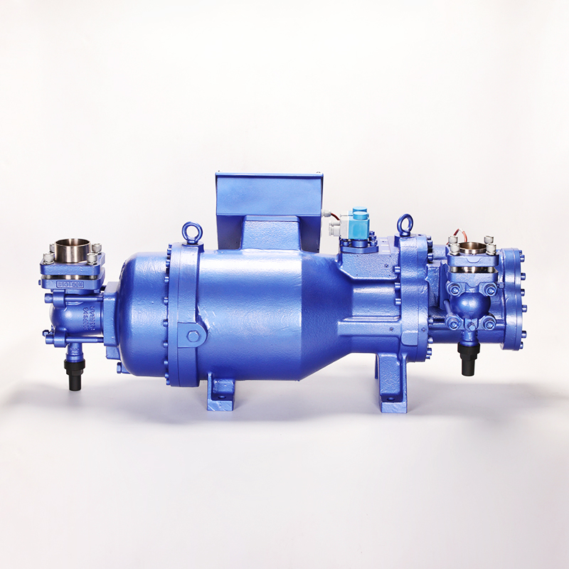
The baseline rotary screw mechanism relies on a simple but highly effective volumetric principle. Refrigerant gas enters a chamber formed between the threads of two meshing rotors. As the rotors turn, this chamber decreases in size and moves away from the suction port. The continuous reduction in volume smoothly increases the gas pressure. Once the chamber reaches the discharge port, the highly pressurized gas exits the compressor. This positive displacement method ensures reliable gas movement regardless of system backpressure.
Precision-engineered, counter-rotating screws deliver a steady, continuous supply of compressed refrigerant gas. Unlike reciprocating compressors that rely on pistons and valves, screw compressors operate without pulsation. The smooth, continuous meshing of the helical rotors eliminates the damaging pressure spikes and vibrations common in piston-driven systems. This pulsation-free delivery protects downstream piping, reduces noise levels, and extends the operational lifespan of the entire refrigeration circuit. The rotors typically feature an asymmetric profile, such as a 5/6 or 4/5 lobe combination, which maximizes the trapped gas volume while minimizing leakage paths.
The two-step compression cycle fundamentally changes how the system handles high-lift applications. The first stage, known as the low-pressure or booster stage, draws in the low-density suction gas and compresses it partially. This intermediate-pressure gas then feeds directly into the second stage, or high-pressure stage. The second stage completes the compression cycle, elevating the gas to the final discharge pressure required for condensation. By splitting the work, neither stage operates outside its optimal thermodynamic envelope. The booster stage handles high volume at low pressure, while the high stage handles low volume at high pressure.
Physical configurations heavily influence system footprint and internal efficiency. The over/under design stands out as a common and highly effective layout. In this configuration, the high-pressure stage sits directly above or alongside the low-pressure stage within a unified cast-iron housing. This setup optimizes the physical footprint, saving valuable plant room space. It also facilitates efficient internal routing of the refrigerant gas between the low and high stages, minimizing pressure drops and internal piping complexity. The internal gas passages are cast directly into the housing, eliminating the need for external crossover pipes that can leak or vibrate loose.
Interstage cooling plays a primary role in maintaining system stability. Compressing gas generates heat. Without intervention, the intermediate-pressure gas entering the second stage would be too hot, causing the final discharge temperature to exceed safe limits. Systems utilize an injected curtain of lubricant or a subcooling economizer circuit to remove heat between the stages. An economizer flashes a small amount of liquid refrigerant to cool the main liquid line, feeding the resulting vapor into the interstage port. This process drastically lowers the discharge temperature and increases the enthalpy difference in the evaporator, boosting overall cooling capacity.
Distributing the compression load across two sets of rotors fundamentally alters the mechanical dynamics of the machine. It reduces the pressure differential across each individual rotor set. This lower differential minimizes thrust loads on the bearings, reduces rotor deflection, and cuts down on internal mechanical vibration. Load balancing ensures that neither stage works to the point of structural fatigue, significantly extending the operational life of the compressor.
Reduced Thrust Loads: Lower pressure differentials mean the angular contact bearings absorb less axial force, preventing premature cage failure.
Optimized Rotor Profiles: The low-stage rotors are cut specifically for high volumetric flow, while the high-stage rotors are cut for high-pressure sealing.
Stable Oil Viscosity: By keeping discharge temperatures well below the oil's breakdown point, the lubricant maintains its protective film across all moving parts.
Facility requirements dictate the specific compressor architecture needed for deep freezing. Engineers must evaluate footprint constraints, environmental regulations, maintenance capabilities, and ambient conditions when selecting equipment. Comparing specific compressor builds based on these dimensions ensures the final system aligns with operational goals. You cannot simply drop a standard commercial compressor into an industrial blast freezing application and expect it to survive.
The choice between a semi hermetic double stage screw compressor and an open-drive design impacts long-term reliability. A semi-hermetic design encloses both the electric motor and the compressor within a single, sealed cast-iron casing. This architecture completely eliminates the need for an external shaft seal. Shaft seals represent the most common point of refrigerant leakage in open-drive compressors. Eliminating this seal makes the semi-hermetic design ideal for strict environmental compliance and specific refrigerants like ammonia or CO2. The internal motor relies on the cold suction gas for cooling, ensuring stable motor temperatures even under heavy loads.
Open-drive systems offer different advantages regarding maintenance accessibility. Because the motor sits outside the compressor housing, technicians can service or replace the motor without opening the refrigerant circuit. However, open-drive systems require external motor cooling and precise shaft alignment. The constant risk of shaft seal wear requires rigorous monitoring to prevent refrigerant leaks and environmental fines. Misalignment between the motor and the compressor shaft will destroy the coupling and the shaft seal within weeks of operation.
Integration into a low temperature screw chiller requires careful component matching. The compressor functions as the heart of the packaged chiller, dictating the volumetric flow rate and the required sizing of both the evaporators and condensers. A properly matched chiller package ensures that the heat exchangers can handle the specific mass flow generated by the two-stage compressor. Undersized evaporators will starve the compressor, while undersized condensers will drive up discharge pressures and negate the efficiency gains of the two-stage design. The expansion valves must also be sized to handle the subcooled liquid coming from the economizer circuit.
Heat rejection strategies directly impact the total compression ratio. Engineers must evaluate the condensing medium carefully. Air-cooled systems rely on ambient air to reject heat, making them susceptible to high summer temperatures. In contrast, a water cooled screw chiller setup utilizes cooling towers or fluid coolers. Water-cooled systems typically offer significantly lower and more stable condensing temperatures. Lowering the condensing temperature reduces the total pressure ratio the compressor must overcome, further improving the efficiency and capacity of the two-stage system. Water-cooled condensers also allow for tighter control over the head pressure during winter operation.
Compressor Architecture Comparison
Feature | Semi-Hermetic Design | Open-Drive Design |
|---|---|---|
Motor Location | Internal, sealed within the compressor casing | External, coupled to the compressor shaft |
Leakage Risk | Extremely low (no external shaft seal) | Moderate to high (relies on shaft seal integrity) |
Motor Cooling | Cooled by suction refrigerant gas | Air-cooled or liquid-cooled externally |
Maintenance Access | Requires opening the refrigerant circuit for motor repair | Motor can be serviced without opening the gas circuit |
Footprint | Compact, integrated design | Larger footprint due to external motor and coupling |
Selecting a two-stage compression system requires a thorough understanding of operational dynamics. Facility managers must weigh the mechanical complexity of dual-rotor systems against the massive efficiency gains achieved at low temperatures. Understanding these trade-offs ensures the system performs optimally across varying load profiles and seasonal conditions. The goal is to maintain a stable evaporation temperature regardless of what happens outside the facility.
Energy density and seasonal ambient temperature swings heavily influence system performance. Condensing pressures fluctuate based on the temperature of the cooling medium. During colder weather, the increased density of the ambient air or cooling water requires less energy for heat rejection. A two-stage system is uniquely capable of capitalizing on these seasonal shifts. By utilizing variable speed drives and advanced slide valve controls, the system can adjust its output to match the lower condensing pressures. This capability allows the facility to maintain tighter, optimized efficiency bands year-round, preventing energy waste during the winter months. The slide valve physically moves along the rotor profile, delaying the start of compression and reducing the volume of gas trapped in the threads.
Maintenance realities differ significantly between single-stage and two-stage systems. A dual-rotor system inherently possesses more moving parts, including additional rotors, bearings, and interstage piping. However, this increased component count does not automatically translate to higher failure rates. Because the compression load is divided, the thermal and mechanical stress per stage drops dramatically. Bearings handle lower thrust loads. Oil maintains its viscosity due to lower discharge temperatures. This reduction in operational stress often extends the mean time between failures (MTBF). Technicians will spend less time replacing degraded oil and worn bearings, provided the system receives proper routine inspections.
Vibration analysis and oil sampling become standard maintenance practices for these advanced systems. Regular oil analysis detects microscopic metal wear before a catastrophic bearing failure occurs. Monitoring vibration signatures on both the low-pressure and high-pressure stages allows technicians to identify rotor imbalance or alignment issues early. Implementing a proactive maintenance schedule maximizes the lifespan of the equipment and ensures uninterrupted deep freezing operations.
Operators should implement the following routine checks to maintain optimal performance:
Weekly Oil Level Verification: Check the sight glasses on the oil separator and reservoir to ensure adequate lubrication volume.
Monthly Vibration Logging: Record the vibration velocity on the bearing housings of both the booster and high-stage sections.
Quarterly Oil Sampling: Pull a sample from the active oil circuit and test for moisture, acid number, and particulate count.
Annual Contactor Inspection: Inspect the electrical contactors in the motor control center for pitting or carbon buildup caused by heavy starting currents.
Deploying advanced refrigeration equipment introduces specific engineering challenges. Recognizing these pitfalls during the specification and installation phases prevents operational downtime. System designers must address oil management, part-load performance, and refrigerant compatibility to ensure long-term success. A poorly commissioned two-stage system will fail just as quickly as an overworked single-stage unit.
Oil management at low temperatures presents a significant hurdle. Deep freezing drastically increases oil viscosity. Thick, cold oil struggles to flow through the evaporator and return to the compressor. Poor oil return starves the compressor bearings of lubrication and coats the inside of the heat exchangers, severely reducing heat transfer efficiency. Mitigation strategies include installing advanced coalescing oil separators on the discharge line to catch oil before it enters the system. Heated oil reservoirs maintain proper viscosity during off-cycles. Precise liquid injection controls ensure the oil remains cool enough to protect the compressor but warm enough to flow freely through the circuit. The oil pump must generate enough differential pressure to force the lubricant into the bearing cavities against the internal gas pressure.
Part-load performance risks inefficiency if not properly managed. Deep freezing facilities rarely operate at 100% capacity at all times. Product loading, ambient temperature drops, and production schedules cause fluctuating freezing demands. Running a fixed-speed compressor at partial loads wastes massive amounts of energy. Integrating Variable Speed Drives (VSD) allows the compressor motor to slow down, matching the exact mass flow required by the facility. Additionally, slide valve capacity control alters the internal volume of the compression chamber, bypassing suction gas to smoothly modulate output from 100% down to 25% without stopping the machine. The PLC must coordinate the VSD frequency and the slide valve position to prevent the motor from stalling at low speeds.
Refrigerant selection dictates the entire thermodynamic cycle. Selecting refrigerants with inappropriate pressure-temperature curves for two-stage compression leads to system failure. If the refrigerant's boiling point is too high, the suction side of the low-pressure stage may drop into a vacuum. Operating in a vacuum draws air and moisture into the system through microscopic leaks, destroying the compressor oil and causing internal corrosion. Engineers must select industrial refrigerants, such as ammonia (R-717) or specific synthetic blends, that maintain positive pressure at the target evaporation temperature. Proper selection ensures robust mass flow and stable interstage pressures.
Verify Suction Pressure: Ensure the selected refrigerant maintains at least 2 psig at the lowest expected evaporation temperature.
Check Glide Characteristics: If using a synthetic blend, account for temperature glide in the evaporator and condenser sizing.
Material Compatibility: Confirm that all O-rings, gaskets, and motor insulation materials are chemically compatible with the chosen refrigerant and oil combination.
Conduct a Load Profile Analysis: Map out your facility's peak and off-peak freezing demands to determine the exact capacity modulation required from the compressor.
Evaluate Heat Rejection Options: Assess your local climate and water availability to decide between an air-cooled condenser or a water-cooled system for optimal condensing pressures.
Specify Oil Management Components: Mandate the inclusion of coalescing oil separators and heated reservoirs in your equipment design to prevent viscosity issues at low temperatures.
Implement Proactive Monitoring: Install vibration sensors and establish a quarterly oil sampling routine to catch mechanical wear before it causes a system failure.
A: It splits the compression ratio across two steps, significantly lowering discharge temperatures, reducing mechanical stress, and maintaining high volumetric efficiency in low-temperature applications. This prevents oil degradation and extends the operational lifespan of the internal bearings and rotors.
A: Two-stage compression is generally recommended when evaporation temperatures drop below -30°C (-22°F). At these extreme temperatures, single-stage systems become highly inefficient, lose mass flow capacity, and become prone to severe overheating and mechanical failure.
A: By enclosing both the electric motor and the compressor within a single, sealed cast-iron housing, it eliminates the need for an external shaft seal. The shaft seal is the most common point of leakage in open-drive compressors, making the semi-hermetic design highly secure.
A: It is the process of cooling the compressed gas between the first and second stages. This is often achieved using an injected curtain of liquid refrigerant or a subcooling economizer. It prevents the second stage from overheating and improves overall cycle efficiency.
A: Water-cooled chillers generally provide lower and more stable condensing temperatures than air-cooled units. This reduces the overall pressure ratio the compressor must overcome, further enhancing the efficiency and cooling capacity of the double stage system.
A: While they possess more internal components, such as two sets of rotors, the reduced thermal and mechanical load on each stage often results in less wear and tear. This reduced stress can potentially extend the lifespan of bearings and lubricants compared to an overworked single-stage unit.
A: Yes, when equipped with internal slide valves or Variable Speed Drives (VSD), they can smoothly modulate capacity to match the exact cooling load. This prevents energy waste and eliminates rapid short-cycling during periods of lower freezing demand.


