
close
Choose Your Site
Global
Social Media
Views: 0 Author: Site Editor Publish Time: 2026-07-06 Origin: Site


Commercial cold storage facilities rely entirely on continuous refrigeration reliability. When equipment fails in these environments, facility operators face immediate product loss and severe revenue impacts. The entire supply chain depends on machines running seamlessly day and night.
Facility managers constantly balance energy efficiency, serviceability, and upfront installation requirements when selecting a reliable cold storage compressor. Variable thermal loads and strict temperature tolerances make choosing the right mechanical core incredibly difficult. You need equipment capable of adapting to sudden shifts in cooling demand.
A Semi-hermetic Reciprocating Compressor offers a unique balance of field serviceability and integrated motor cooling. We will explore how these robust machines operate and why they remain the standard for mid-to-large capacity facilities. You will learn the mechanical principles, common risks, and maintenance realities required to keep them running efficiently.
Integrated but Accessible: Unlike fully sealed units, semi-hermetic reciprocating compressors house the motor and compressor in a bolted casing, allowing for on-site rebuilding and maintenance.
Operating Principle: They utilize piston-driven compression (suction and discharge strokes) driven by a motor that is actively cooled by returning refrigerant gas.
Cold Storage Fit: Ideal for applications requiring robust capacity control (via cylinder unloading) to handle the varying thermal loads typical of commercial cold storage.
Decision Driver: The primary advantage over open-drive or fully hermetic models is the elimination of shaft seal leaks combined with long-term asset repairability.
Understanding the basic mechanics of these machines helps operators maintain peak efficiency. The internal system functions much like an automobile engine. Pistons move vertically inside cylinders to compress refrigerant vapor. This continuous cycle maintains the necessary pressure differentials across the entire refrigeration loop.
The mechanical process relies on alternating strokes. The crankshaft rotates, pulling the connecting rods and pistons downward. This specific movement creates a low-pressure void inside the cylinder.
Suction Stroke: The piston descends inside the cylinder bore. This action drops the internal pressure below the suction line pressure. Low-pressure refrigerant vapor flows into the chamber.
Compression Stroke: The crankshaft forces the piston back upward. The chamber volume shrinks rapidly. This action squeezes the trapped vapor, significantly raising its pressure and temperature.
Discharge Stroke: The piston reaches the top dead center of its stroke. The high-pressure gas forces the discharge valve open. The hot vapor exits the cylinder into the discharge line.
Expansion Phase: A tiny amount of high-pressure gas remains in the clearance volume. As the piston begins moving down again, this residual gas expands before new suction vapor can enter.
Valve plates sit directly above the cylinders. They contain flexible metal strips called reed valves. These valves operate purely on pressure differentials. They do not use mechanical cams or electronic actuators.
During the downstroke, cylinder pressure drops below suction line pressure. This difference forces the suction reed valve to bend open. Vapor rushes in. During the upstroke, cylinder pressure exceeds the suction pressure. This forces the suction valve closed. As pressure continues climbing, it eventually exceeds the discharge line pressure. The discharge reed valve bends open, allowing gas to escape. These valves flex thousands of times per minute. They require clean refrigerant to avoid stress fractures.
Heat is the enemy of electrical motors. Traditional open-drive motors use ambient air and external fans for cooling. A semi-hermetic unit takes a more integrated approach. The returning low-temperature suction gas acts as the primary cooling medium.
Before the low-pressure vapor enters the cylinders, internal channels route it over the motor windings. The cool gas absorbs heat generated by the electrical stator. This design prevents motor overheating without requiring external cooling fans. It allows the machine to operate safely inside enclosed mechanical rooms. However, operators must maintain adequate suction pressure. If suction gas flow drops too low, the motor can rapidly overheat.
Continuous metal-on-metal movement requires robust lubrication. Most commercial units employ an internal, reversible oil pump driven directly by the crankshaft. This pump forces specialized refrigeration oil through tiny channels inside the crankshaft. The oil lubricates the main bearings and connecting rod journals.
Smaller models often use splash lubrication. A small scoop on the connecting rod dips into the oil sump during every revolution. It flings oil upward to coat the cylinder walls and wrist pins. Regardless of the delivery method, proper oil viscosity remains crucial. The oil must protect moving parts under intense heat and continuous operation.
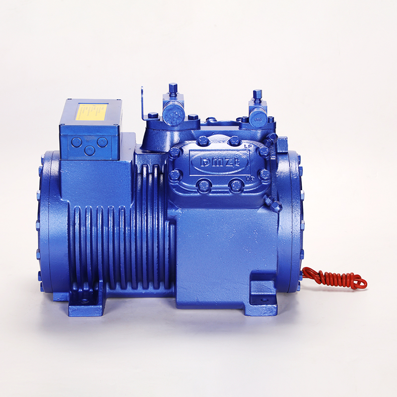
Engineers classify commercial compressors primarily by their outer casing. The housing dictates how you service the machine. It also determines the system's susceptibility to refrigerant leaks. Choosing the right design impacts your long-term operational budget.
Hermetic compressors feature a fully welded steel shell. Manufacturers seal the motor and mechanical parts permanently inside. You cannot open them. When a fully hermetic unit fails, you must cut it out of the piping and throw it away. They suit light commercial applications like reach-in coolers. They offer lower upfront costs but zero repairability.
A semi-hermetic casing uses heavy cast iron. Heavy-duty bolts and specialized gaskets seal the components together. Technicians can unbolt the cylinder heads. They can access the valve plates, pistons, connecting rods, and electrical stators. If a valve plate shatters, you replace the plate. You do not replace the entire machine. This field repairability makes them ideal for heavy industrial use.
Open-drive systems separate the motor from the compressor block. An external electrical motor drives the crankshaft via belts or direct couplings. The crankshaft must protrude through the compressor casing. This design requires a mechanical shaft seal to keep refrigerant inside.
Shaft seals degrade over time. They eventually leak expensive refrigerant into the atmosphere. A semi-hermetic design eliminates this protruding shaft. The casing encloses both the motor and the mechanical block. It significantly reduces the risk of costly refrigerant leaks. It maintains heavy-duty performance while protecting environmental compliance.
Facility managers must consider long-term asset repairability. Buying a bolted-casing model enables targeted component replacement. If a power surge burns out the electrical stator, a technician can swap the stator on-site. You avoid the massive expense of purchasing a completely new unit. You also save on heavy rigging costs and extended downtime. This repair-focused design stretches the capital investment over decades.
Compressor Housing Design Comparison | |||
Feature | Hermetic | Semi-Hermetic | Open-Drive |
|---|---|---|---|
Casing Type | Welded steel shell | Bolted cast iron | Separate motor and block |
Repairability | None (Replace-on-failure) | High (On-site rebuilds) | High (Easy motor swaps) |
Leak Potential | Very Low | Low (Gasket seals) | High (Shaft seal wear) |
Target Application | Light commercial coolers | Mid-to-large cold storage | Ammonia systems / Marine |
Cold storage facilities rarely experience steady cooling loads. Product arrives warm and needs rapid chilling. Forklifts open dock doors, letting warm air inside. At night, doors remain closed and the thermal load drops. The refrigeration core must adapt dynamically to these changing conditions.
Operating at full capacity during low-load periods wastes immense electrical energy. It also causes the machine to cycle on and off rapidly. This "short-cycling" destroys electrical contactors and shortens motor life. To prevent this, these machines utilize "cylinder unloading" mechanisms.
When the cold storage load decreases, the system detects a drop in suction pressure. An electronic controller activates solenoid valves located on the cylinder heads. These valves manipulate internal gas pressures to hold specific suction reed valves open. The deactivated cylinders simply pump gas back and forth without compressing it. A six-cylinder machine might drop to four, or even two active cylinders. This capacity modulation saves energy and keeps the machine running continuously at lower outputs.
Deep freezing applications push mechanical limits. Blast freezers often require temperatures around -20°F or lower. Achieving these temperatures means operating at very low suction pressures. Compressing this thin gas up to high condensation pressures creates an extreme compression ratio.
High compression ratios generate dangerous discharge temperatures. If discharge gas gets too hot, the lubrication oil breaks down and loses its protective qualities. To combat this, systems utilize liquid injection. A specialized valve injects a tiny amount of liquid refrigerant directly into the suction chamber. This liquid absorbs heat as it vaporizes, cooling the cylinders. For ultra-low temperatures, engineers employ two-stage compression. They use two separate machines to step the pressure up gradually, avoiding extreme heat spikes.
Modern facilities increasingly pair these units with Variable Frequency Drives (VFDs). A VFD changes the electrical frequency supplied to the motor. This alters the motor's rotational speed, allowing precise capacity matching.
Soft Starting: VFDs slowly ramp up the motor speed. This reduces massive mechanical jolts and limits inrush current spikes.
Precise Control: Instead of dropping capacity in strict 25% or 33% steps (like cylinder unloading), a VFD offers smooth, continuous capacity modulation.
Energy Reduction: Slowing the motor during off-peak hours drastically cuts electrical consumption.
Stable Temperatures: Continuous, speed-matched operation provides incredibly tight temperature tolerances inside the refrigerated space.
No single technology fits every facility perfectly. Facility engineers must evaluate capacity, environmental regulations, and physical constraints before committing to a specific design. Choosing incorrectly leads to excessive maintenance intervals and poor system performance.
This technology dominates the mid-to-large commercial sector. You will typically find them ranging from 5 horsepower up to 50+ horsepower per unit. For massive distribution centers, engineers arrange several units together on a parallel rack system.
A parallel rack connects multiple machines to a single shared suction and discharge header. A master controller turns individual units on or off based on the overall facility demand. This configuration provides built-in redundancy. If one unit fails, the others continue running to protect the perishable inventory. Reciprocating models excel in these multi-compressor arrangements due to their robust oil management capabilities.
Environmental regulations constantly reshape the refrigeration industry. Traditional high-GWP (Global Warming Potential) gases face strict phase-outs. Engineers must select equipment compatible with modern, eco-friendly alternatives. Modern semi-hermetic units handle this transition exceptionally well.
Manufacturers offer models specifically built for high-pressure CO2 (R-744) transcritical systems. They also design units compatible with mildly flammable A2L blends and modern HFCs. You must verify compatibility before purchasing. Different refrigerants require specific synthetic oils and distinct elastomer gaskets. Using the wrong gas degrades the internal seals and destroys the lubrication properties.
Refrigerant Compatibility Summary | ||
Refrigerant Category | Common Examples | Adaptability & Hardware Needs |
|---|---|---|
Traditional HFCs | R-404A, R-448A | Standard POE oils, widely supported, easy retrofit. |
Natural Refrigerants | CO2 (R-744) | Requires heavy-duty iron castings to handle extreme transcritical pressures. |
A2L Blends (Mildly Flammable) | R-454A, R-454C | Requires specific electrical terminal venting and certified non-sparking components. |
Physical realities dictate installation limits. These machines feature heavy cast-iron blocks. They possess a significant physical footprint compared to compact scroll models. You must account for this weight during structural planning.
Acoustics also present a challenge. Piston movements create inherent vibration and noticeable noise. Scroll compressors generally run much quieter. If your mechanical room sits adjacent to an office space or a noise-sensitive property line, you must implement mitigation strategies. Engineers specify specialized vibration isolation mounts—usually heavy-duty springs or thick neoprene pads. They also install flexible discharge line loops to prevent vibration from fracturing the rigid copper piping.
Even the most durable machinery fails under poor operating conditions. System designers must engineer safeguards against specific piping risks. Once installed, technicians must follow disciplined maintenance routines. Neglect quickly destroys the internal components.
A compressor operates purely as a vapor pump. It cannot compress liquids. If unevaporated liquid refrigerant travels down the suction line and enters the cylinders, disaster follows. This phenomenon is known as liquid slugging.
When the piston attempts to compress an incompressible liquid, the internal hydraulic pressure spikes instantly. This violent force shatters valve plates, snaps connecting rods, and blows out head gaskets. Mitigation requires precise superheat control at the evaporator expansion valves. Engineers also install suction accumulators near the machine. An accumulator acts as a holding tank. It catches returning liquid droplets and boils them off before they can enter the motor housing.
Refrigeration oil travels through the entire piping network alongside the refrigerant. In sprawling cold storage facilities, piping runs stretch for hundreds of feet. If vapor velocity drops too low, oil gets trapped in the distant evaporator coils. This is called oil logging.
When oil logs in the evaporators, it starves the compressor crankcase. Operating without oil destroys the main bearings within minutes. Highlight the necessity of proper piping design. Vertical suction risers require specific P-traps to push oil upward. Large systems also utilize mechanical oil separators on the discharge line. These devices catch hot oil leaving the cylinders and route it safely back to the crankcase.
You cannot install these machines and forget them. They demand active oversight. Fortunately, their accessible design makes routine checks straightforward.
Regular Oil Analysis: Technicians should extract oil samples annually. Lab testing reveals metal shavings, high acidity, or moisture contamination before catastrophic failure occurs.
Electrical Inspections: Inspect contactors and tighten electrical terminals. Loose connections cause voltage drops and excessive heat at the motor terminals.
Valve Plate Checks: Monitor discharge temperatures and pumping efficiency. If capacity drops, technicians can unbolt the heads and visually inspect the reed valves for hairline fractures.
Filter Replacements: Swap out suction filter cores and liquid line driers to catch debris and absorb internal moisture.
Bypassing internal oil pressure safety switches to keep a nuisance-tripping machine online.
Failing to install crankcase heaters, leading to refrigerant migrating into the oil during off-cycles.
Ignoring abnormal vibration, which quickly fatigues the rigid copper discharge lines.
When designing the mechanical room, you must plan for future service. The bolted design offers great repairability, but only if technicians can physically reach the bolts. Ensure the piping layout leaves enough physical clearance to pull the massive electrical stator horizontally. Do not install the unit tight against a block wall. Leave vertical clearance for lifting tackle to remove heavy cylinder heads and valve plates in-situ.
Semi-hermetic reciprocating compressors remain a cornerstone of industrial refrigeration due to their ruggedness, repairability, and adaptability to partial loads. Their unique ability to handle variable thermal loads through cylinder unloading makes them perfect for dynamic freezing environments. The integration of motor cooling via suction gas ensures reliable operation within confined mechanical spaces.
Advise your engineering team to conduct a lifecycle energy and maintenance analysis before specifying equipment for your facility. You should compare the higher upfront cost and ongoing maintenance needs against the long-term energy savings of capacity control. Furthermore, evaluate the immense financial benefit of avoiding full-unit replacements. When appropriately sized, protected from liquid slugging, and meticulously maintained, these machines will protect your critical inventory for decades.
A: Typically 10–15+ years with proper maintenance. This operational lifespan extends significantly longer than fully hermetic models due to robust rebuild capabilities. Routine oil changes, prompt valve plate replacements, and strict superheat control help maximize longevity.
A: Yes, the bolted casing design allows technicians to replace valve plates, pistons, and stators without removing the main compressor block from the piping network. This localized serviceability drastically reduces facility downtime and heavy rigging expenses.
A: Scroll compressors are generally quieter, have fewer moving parts, and run highly efficiently at smaller capacities. Reciprocating units are better suited for larger, highly variable loads where field serviceability and heavy-duty capacity modulation remain strict operational requirements.


